1. Torque 101
1.1 What is torque?
In classical mechanics, torque is a numerical representation of a twisting or rotational force around an axis. Expressed in terms of vectors, Torque (τ) is equivalent to the Cross Product (×) of the Linear Force (F) and Radius (r). Put together, the equation is written as follows:
![]()
This equation can be visually expressed like so:
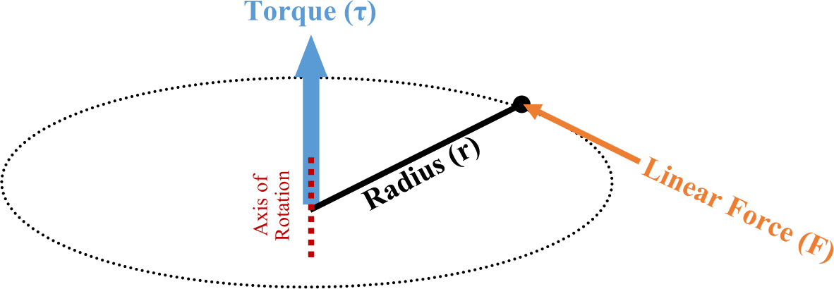
The resultant Torque will always coincide with the axis of rotation, which will be perpendicular to both initial Force and Radius vectors.
Note that the above diagram is expressed in three dimensions and assumes the resultant axis of rotation is unknown. In most practical applications, the axis of rotation is fixed (or at least known) so the above cross product can be converted to simple multiplication, flattening the above diagram into a 2-dimensional version as shown below:
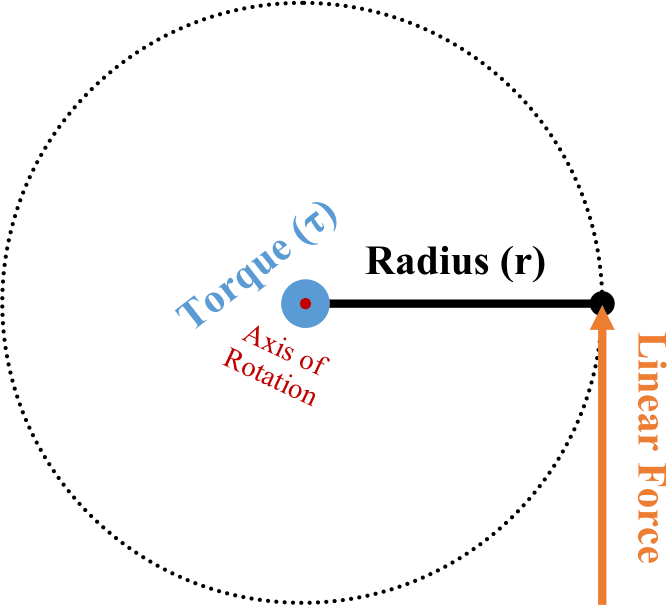
This simplified version is convenient, since multiplying two numbers is much easier than attempting a cross product. However, for this version to remain true it is important to maintain a fixed axis of rotation and to keep the radius and linear force perpendicular to each other. Assuming those two items are enforced, the equation becomes Force (F) multiplied by Length (L). When convenient, we can also substitute Weight for Force since weight is just a measure of the force of gravity upon the mass of an object. Summarized as simply:
![]()
1.2 How does this apply to my application?
If the 2-dimensional figure from above is applied to a manual torque tool such as a Beam Wrench, then Length becomes the working length of the tool, and Force becomes the amount of pull required to reach the target Torque. With most torque tools, including the beam wrench, the working length is fixed, and the applied force is varied to achieve the desired torque. Some manufacturers indicate this working distance by designing the handle to include a line marking the location at which force should be applied. Other manufacturers will mount the handle on a pin so that it may swivel, ensuring that the applied force is always centered at the exact working distance.

Tools such as Torque Multipliers also work on the same working distance principle but place a reduction gearbox in between the application of input force and output force, increasing the resultant output with mechanical leverage. Hydraulic wrenches use principles of working distance and force, but do not maintain perpendicularity between the distance and applied force, since they can generate enough force to negate the inefficiency discussed in the next section.
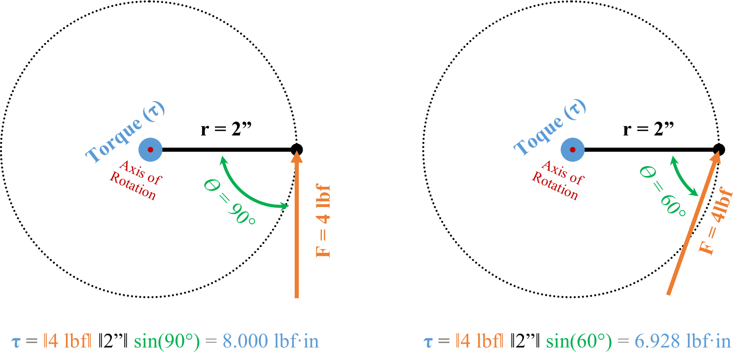
The formula τ = F L is a simplified version of the formula for Torque. The full version is the magnitude of the Force (F) multiplied by the magnitude of the Radius (r) multiplied by the sine of the angle Theta (ϴ). Where Theta is the angle between the Force and Radius vectors, less than or equal to 180°, when both are drawn from the same origin point (the axis of rotation). Otherwise written as:
![]()
We could simplify the equation earlier since the Radius and Force components were assumed to be perpendicular to each other and sin(90°) = 1. Should this not be the case, then the angle between the components, ϴ, becomes relevant again and needs to be accounted for.
Additionally, since the sine of an angle can never be greater than 1, any angle other than 90° will only serve to reduce the amount of Torque generated for the same Radius and Force, as shown in the following example:
In addition to maintaining a 90° angle between the lever length and linear force, it is also important to ensure that the axis of rotation is perpendicular to the plane of the Force and Distance components. If the perpendicularity of the axis of rotations is not maintained, then the true axis of rotation will not line up with the physical axis of rotation and a loss of torque similar to that shown in the above example will occur. Physically, this can also introduce friction and non rotational forces into the torque application that will complicate and further reduce the accuracy and efficiency of the torque system.
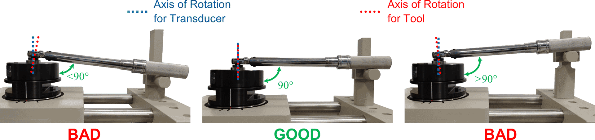
In the above image, the left and right configurations will result in a discrepancy between the applied torque and the torque indicated by the wrench. The center example is ideal and the recommended setup for any torque application, including both the installation of fasteners and calibration of torque tools.
1.3 Example #1 Dead Weight Calibration
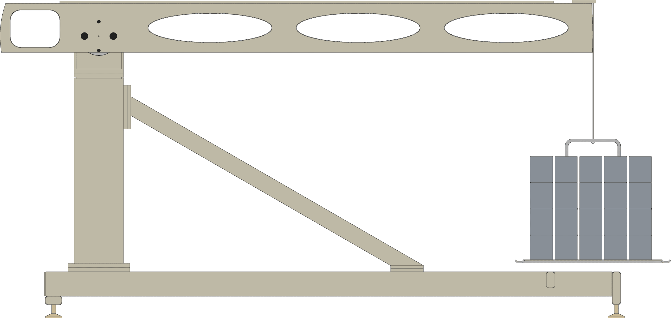
A TSD10011 transducer rated for 10000 lbf·ft is due for calibration. Having both the TSD10052, a 5ft moment arm, and the TSD20052-SP, a 10ft moment arm, and all relevant equipment to use them, how much weight is required for each arm to exercise the transducer at capacity?
Since the AKO transducer calibration stand can reliably keep all component forces perpendicular to the other component forces, the simpler Torque formula τ = F L can be used.
Knowing that the working distance of the TSD10052 is 5ft and the working distance of the TSD20052-SP is 10ft, the following can be calculated:
τ = F L → F= τ ÷ L → F = 10000 lbf·ft ÷ 5 ft = 2000 lbs of weight
τ = F L → F= τ ÷ L → F = 10000 lbf·ft ÷ 10 ft = 1000 lbs of weight
To calibrate a 10000 lbf·ft TSD10011 torque transducer, 2000 lbs of weight would be required for the TSD10052 and only 1000 lbs of weight would be required for the TSD20052-SP.
1.4 Example #2 The Beam Wrench
Given an accurately calibrated beam wrench with a working distance of 1.5ft, how much force need be applied to the handle to achieve a desired installation force of 10 lbf·ft?
τ = F L → F= τ ÷ L → F = 10 lbf·ft ÷ 1.5 ft = 6.667 lbf of force